3.2. Overall workflow
Overall computation workflow is shown in Figure 3.2.1. Starting with runoff depth from netCDF or coupler (e.g. CTSM coupling),
Remap runoff depth [m/s] to river network HRU (Hydrologic Response Unit or simply catchment), \(R_{lat}\), if runoff is given at hydrologic model HRU
Convert \(R_{lat}\) from depth unit to volume (\(R_{lat}\) times HRU area) to get lateral runoff volume (\(q_{lat}\)) [m3/s]
Perform hillslope routing to delay lateral runoff volume, if travel time of runoff is not counted outside mizuRoute.
Route inflow from upstream and add delayed lateral discharge to routed inflow at each river reach outlet.
The hillslope routing method currently uses a simple unit hydrograph based on gamma distribution (only one method available) to delay instantaneous runoff. See the next section Hillslope routing scheme).
The river reach or lake routing needs to be performed in the order of upstream-to-downstream to complete the routing in the entire river network. The section Navigate river network describe how mizuRoute navigates the river network from the headwater to outlet of the basins.
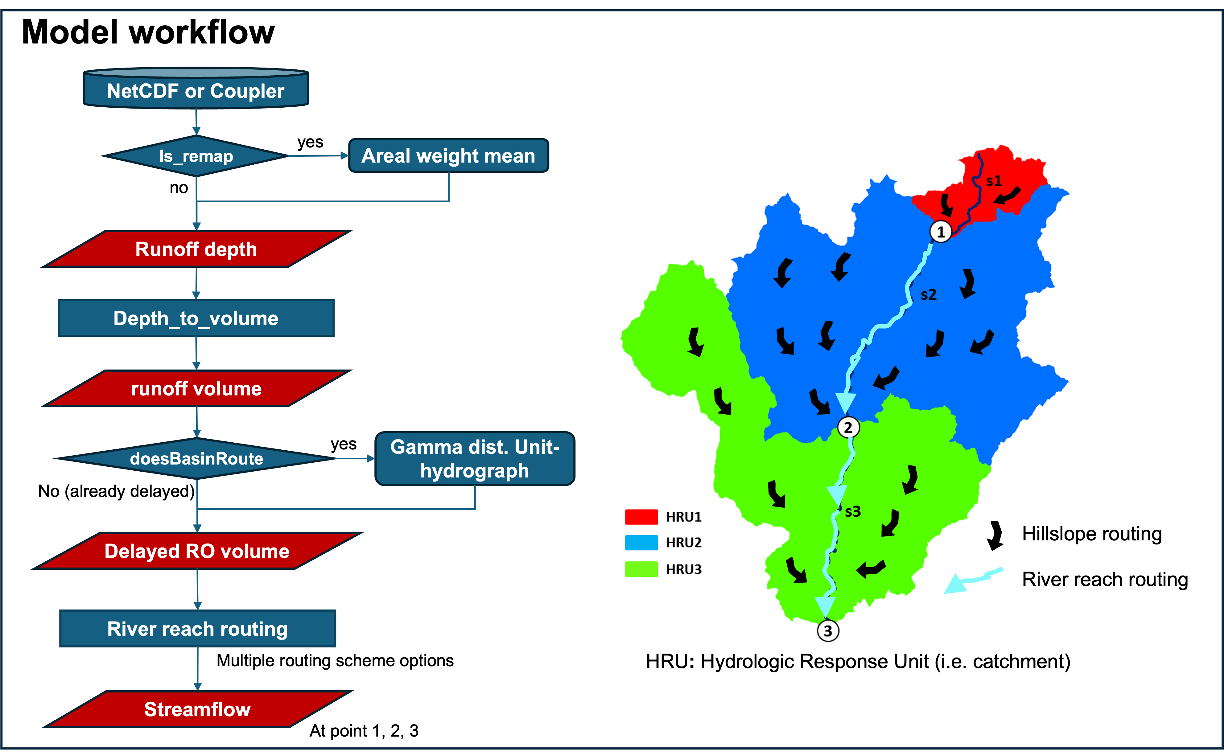
Figure 3.2.1 Overall routing procedures from runoff input into model to streamflow computation.